Video Mod for the Atari 7800


Better Video
There are limits to the Atari 7800's video quality. This project tries to compromise between simple enough to build and best quality available.


Atari 7800 Video Mod Construction
One day I decided that I'd got a headache from the RF interference on my 7800's display for the last time. I was not about to give up playing games on my 7800. And I knew there was a nice, clean video signal inside the 7800--all I needed to do was bring it out.
Once I got started, I decided to be even less compromising. Sure, I could have pulled the composite video off of the input to the RF modulator and put that through an amplifier. In fact, I did that with a breadboarded arrangement. I was less than impressed with the colors I got.
Instead, I decided to go with an S-Video output. In S-Video, also known as S-VHS, the luma and chroma signals are run separately to the display device.
A breadboard arrangement that used a thick cluster of clip jumpers to connect to the board convinced me that this would in fact be the way to go. The video I got off the breadboard was so nice that I played with that hooked up to the system for two days before I buckled down to building the permanent version of the circuit.
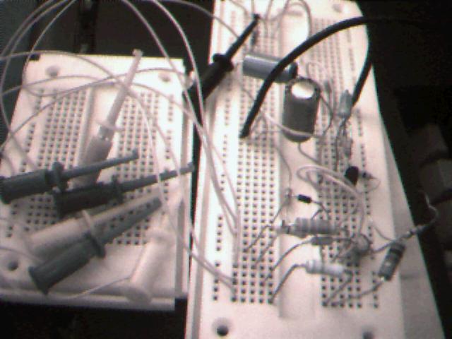
The prototype for the video mod.
The Circuit and Parts

The schematic for the video mod.
Bill of Materials
- Q1 2N3904 Transistor.
- CR1 Any signal diode. See below.
- C1 100uF Electrolytic Capacitor.
- C2 10uF Electrolytic Capacitor.
- C3,C4 1uF Tantalum Capcitor.
- R1 820 ohm Resistor.
- R2 1.6Kohm Resistor.
- R3 3.3Kohm Resistor.
- R4 6.8Kohm Resistor.
- R5 10Kohm Trim Potentiometer.
- R6 1.8Kohm Resistor.
- R7 2.0Kohm Resistor.
- R8 10 ohm Resistor.
- R9,R10 68 ohm Resistor.
- R11 1.2Kohm Resistor.
- R12 200 ohm Resistor.
- R13 18Kohm Resistor.
- R14 6.8Kohm Resistor.
- J1, J2, J3 RCA Bulkhead Connector.
- The Board A small prototyping PC board. See below.
Part Details and Part Substitutions
Q1
Stick with the 2N3904 here. The case style does not matter. These are available at Radio Shack in bubble packs for about fifty cents apiece. If you buy in small quantities from companies like JDR or Jameco, they go for about a dime apiece.
Radio Shack Part Number:276-2016
Jameco Part Number:38359
JDR Part Number:2N3904
CR1
I used an FD333 here just because that's what I happened to have plenty of on hand. Chances are you don't have a bunch of these on hand. A 1N4001 will work fine here, and it's a common diode.
Radio Shack Part Number:276-1101
Jameco Part Number:35975
JDR Part Number:1N4001
C1
You can use an electrolytic capicitor with either radial or axial leads, whatever suits your layout better. Just make sure you get the positive lead in the right place, and the negative lead where it belongs. I specify a 100uF capacitor, but a 220uF will work just as well, this is not a critical value. I prototyped the unit with a 220uF capacitor because that's what I happened to have handy. I dug out a 100uF cap to use in the final version because I had one that was a little smaller than 220uF part I used on the breadboard.The cap should be at least a 16V part, a 25, 35 or 50V part will work just as well, it will just be a bit bigger.
Radio Shack Part Numbers (pick any one):272-956, 272-1028,
272-1029, 272-1016
Jameco Part Numbers: 10911, 93761
JDR Part Numbers: 100R16, 100A16
C2
A 10uF electrolytic, either radial or axial leads, 16V or better.
Radio Shack Part Numbers (pick any one):272-1013, 272-1025
Jameco Part Numbers: 93577, 94211
JDR Part Numbers: 10A100, 10R63
C3,C4
A 1uF tantalum cap is the thing to use here. You could substitute any other 1uF non-polar cap here, too.
Radio Shack Part Number: 272-1434
Jameco Part Number: 33662
JDR Part Number: T1.0-16
Resistors
None of the resistors is critical in terms of whether it needs to be 1/8 watt, 1/4 watt or whatever. Nor are close tolerances required on the values. Standard carbon comp or carbon film resistors will work fine.I used everything from standard carbon comp resistors to high-precision military parts depending on what came to hand first, it doesn't matter. Where I didn't have a specific value, I used two resistors in series to get the same resistance value. For example, my 6.8K resistor is a 3.0K in series with a 3.8K.
Also, R9 and R10 would be 75 ohm resistors in a perfect world. These are available, but not common. Anything from 68 ohms to 82 ohms is OK here, just make sure R9 and R10 are the same.
Potentiometer
The pot is a 10K trimpot. A 15K trimpot would be OK, too, it would just be harder to get a fine adjustment on unless you use a multiturn pot. I use a square single turn pot. You'll want a nice small trimpot here, a regular pot wouldn't fit well inside the RF shield of the 7800.In my perusal of the Radio Shack catalog, I didn't find a 10K trimpot that is stocked in stores (2XX-XXXX number), just ones that need to be ordered (9XX-XXXX number). If you need to order it, just get whatever 10K trimpot is cheapest.
Jameco Part Number: 43001
JDR Part Number: 72PR10K
The Connectors
I used three RCA bulkhead connectors because I couldn't come by a bulkhead S-Video connector when I wandered into Radio Shack. I wanted to use a single RCA bulkhead connector for audio, and the S-Video connector for the chroma and luma. Instead I have one RCA connector for each of Chroma, Luma, and Audio. I made a cable to go from the two RCA connectors for chroma and luma to plug into my TV's S-Video input.
Radio Shack Part Number:274-346 (four in a pack)
Jameco Part Number:159484
JDR Part Number: (Not Found)
I also considered using a DIN jack and making the output the same as a C-64's video port since that would not only allow me to use the C-64 monitor cables that I already have for the Commodore monitor, but it would also give me the incentive to make the C-64 S-Video cable that I've been thinking of making for some time now. But I decided to go with the 3 RCA jacks instead.
The Board
I built the circuit up on a board I happened to have handy, a small Radio Shack prototyping PC board. Any similar board, or a piece of perfboard would do fine.
Radio Shack Part Number:276-150 (the board I used.)
Jameco Part Number: 105099 (a different board that would do as
well as the one I used.)
JDR Part Number: JDR-BB65 (a piece of perfboard. Use a chunk
of it.)
Construction of the Circuit Board
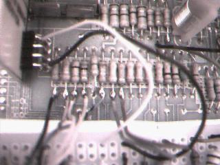
Since I don't know what you're building up your circuit on, I'm just going to give general guidance on the actual construction of the circuit.I laid my circuit out so that the signal inputs from the 7800 were all on one edge of the PC board and the outputs were all on the opposite edge. Each output was paired with a ground connection. Here is a picture of my board from just before I connected the output wires:
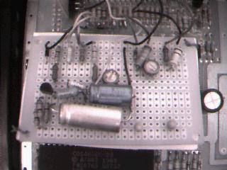
You'll notice a second pot on the board on the Chroma signal. This pot turned out not only to be unnecessary, but useless, so I deleted it from the design. Also, the pot in the above picture that I had on brightness did not have enough range, so in later pictures you'll see a square blue pot that I used to replace it.
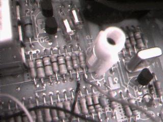
And below is a shot of the completed board sitting in the 7800. The wires on the left are the outputs running up to the connectors I placed on the left hand side of the console. Placement of the connectors was tricky, I had to leave room on the outside for RCA plugs with a thick insulating boot around them, as well as room for fingers to grip the plugs while plugging them in and pulling them out.
I also needed to leave room inside for the 7800's PC board. This was a real balancing act. There are other places you can mount the connectors, or you can run them out of the box on cables, and use inline connectors. If you have an older 7800 you will have a connector port here so you'll have to figure out something else.
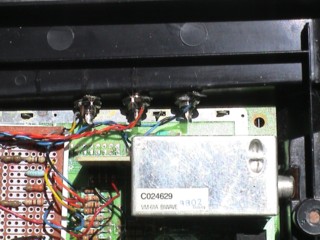 The connectors from inside the case. |
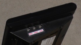 The connectors as seen from outside the case. |
Be careful as you assemble the PC board to make sure your circuit matches the schematic. Once you've finished the PC board, here is where to attach the leads to the 7800's internals:
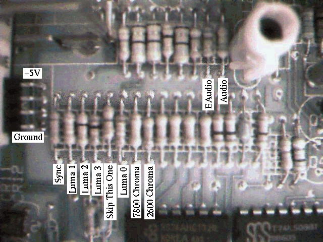
The labels are placed immediately below the resistor lead where
you will want to pick up the signal. Note that the Luma0 signal
is out of order, over by the Chroma signals. Be careful to get
the luma singals wired to the correct place, or your brightness
levels will be really hosed.
The power is picked off of the connections for the RF modulator. The connection toward the front of the unit is a ground, the one at the back of the unit is +5V. The composite video/audio signal that the RF convertor uses is on the lead next to the +5V connection.
I picked off the signals using some Bell wire, a solid copper wire that's about 24 guage in size. I prefer to use solid wire for things like this, since I don't have to worry about stray strands of wire shorting things out. If you use stranded wire, twist it and tin it, then form it into hooks before you connect it inside the 7800. This will allow you to see any stray strands and nip them off before they cause any trouble.
Here's a look at my connections.
The video and power connections to the 7800.
The audio connections to the 7800.
Insulation
To prevent any short circuits from the bottom of the project board touching things underneath it, I used a piece of cardstock attached to the project board. To save myself trouble in reverse-engineering my own circuit in years hence, I took advantage of this convenient space to draw a circuit diagram of the mod board.
The insulator, with a handy schematic.
Adjustment of the Circuit
I spent some time trying to reduce the amount of adjustment needed for this circuit, in fact my original goal was to have no adjustment at all. But the variability of different display devices and of different components made me leave one potentiometer in to adjust the brightness level.In my case, I plan to use two different displays, a composite monitor and my TV. The TV display is not as bright as the monitor's with the monitor and TV at their nominal settings.
Also, between the breadboard circuit I built and the permanent one I found that there was a pretty significant variation in the transistors. I don't have a curve tracer on hand to compare the two transistors against each other, but while I was able to get all the adjustment in brightness I needed out of a 1K pot in the breadboard version, I needed at least a 5K pot in the permanent model to get the same range of adjustment. So I decided to put in a 10K pot to be safe.
So if you are planning to use more than one display for your system, I recommend doing the adjustment using both, going back and forth between them to get the best compromise on brightness adjustment.
Also, you will want to check the display with both 2600 and 7800 cartridges. And for each type of cartridge, use at least one game that has a black background, and another that has the display pretty well filled with color.
The cartridges I used are:
- 7800-Dig Dug (filled display)
- 7800-Centipede (black background)
- 2600-Battlezone (filled display)
- 2600-Galaxian (black background)
I also dropped in several other cartridges to check the adjustment including both versions of Ms. Pac-Man, 2600 Pitfall, Xevious, etc.
Performing the Brightness Adjustment
Start the system with your filled display 7800 cartridge in it. Adjust the brightness up until the sides of the image pull to the right at the brighter parts of the image. Then turn the brightness down until the image is stable, with straight sides on both sides.Now turn the system off and put in your black background 7800 game. Turn it on and make sure that the dark objects are clearly visible. Dark greens seem to be the worst. Adjust the brightness up until you can see them well.
Now put back the filled-screen 7800 cart and adjust back down again until you get the display stable. You'll probably want to do it with a finer hand than the first time through.
Go back and forth until you get an acceptable image. If you must err, err on the side of darker.
Now put in your 2600 filled-screen cart and make sure the image is still not too bright. It should not be, since the 7800 image has slightly greater range than the 2600 display (Luma0 is not used by the 2600 mode).
Check things out with your 2600 black background game cart as well. Make adjustments as necessary. Whenever you make adjustments in the 2600 mode, go back through both your 7800 carts and check things and make any tweaks necessary before going on.
While you are doing the adjustment, make sure that you are using decent cables. The first time I ran through the adjustment process, I was using clip jumper cables instead of proper video cables. I was having a hard time getting the dark greens to be visible without having the brightness too high for the filled-screen games. Once I made up my S-Video cable, I found that I had plenty of room for adjustment. I just turned the brightness down a bit from where it had been and everything was fine. After that it was just a matter of cycling through several different carts to make sure the display looked good with everything I like to play commonly.
And the display is spectacular. I can see the dark green ships in 2600 Galaxian that I couldn't see through the RF modulator. I feel like I'm in an arcade when I play Ms. Pac-Man and Centipede. The colors are all bright and the display is crisp. And the screen isn't covered with snot from some kid sneezing all over it, so it's even better than the arcade!
Closing the Box
Thanks to all these new connectors, the top half of the RF shield would no longer fit in its place. So I had to take a pair of metal shears to it to enlarge the hole in it that was intended for the expansion port never installed on this unit. I added about half an inch to the port on the side toward the front of the box, and about three quarters of an inch to the side toward the rear of the box.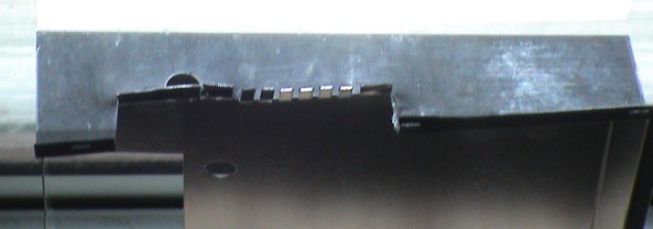
The enlarged opening in the RF shield.
The S-Video plug is available at Radio Shack for about five
bucks, I haven't found it at any other suppliers that sell in
small quantities yet. The part number is 278-451. What I did was
also pick up a high quality audio patch cable that is six feet
long. I clipped off the RCA plugs at one end of the audio patch
cable (with enough cable left on them to have them still be
useful for breadboarding and other projects), and connected the
appropriate wires to the S-Video connector.
Remember to put the backshell on the cable before soldering!
Then I took the center conductor of the line that went to the
white RCA plug and soldered it to pin 3, the shielding went to
pin 1. The red plug's center conductor went to pin 4, and its
shielding to pin 2. The strain relief was then crimped around
the cable sheathing, and some extra shielding strands from both
sides were soldered to the strain relief.
This put the Luma on the white plug (white=brightness) and the
Chroma on the red plug (red=color). If you want the pinout for
S-Video, you can get it here at the
Hardware Book.
The S-Video Cable
If you want to put the output of your newly-enhanced 7800 into
an ordinary composite video port of a display, use a Y-cord to
bring the Chroma and Luma outputs together then run these into
the Composite input of your display. If you want to get the full
value of your 7800-plus, you can either use RCA patch cables
with a composite monitor that accepts separate Chroma and Luma
inputs, like the Commodore composite monitors, or you can make a
cable to go from your 7800 to an S-Video plug.
Thanks to
Jay Tilton
for his original posting on which my design
was based, and thanks to
Lee Krueger
for making sure it is still
available on the web
here.
Thanks to Matthias Hartl for catching an error in the type of tranny shown in the schematics, and to B. Cross for catching that I dropped R13 and R14 out of the B.O.M. at some point.